Selecting Microfluidic Tubing
Microfluidic systems have revolutionized various fields, from biotechnology to analytical chemistry, providing precise control over small volumes of fluids. One critical component in these systems is microfluidic tubing, which plays a pivotal role in ensuring efficient and reliable fluid transport. Here are general guidelines for choosing the right microfluidic tubing to optimize your experiments.
How to choose the right microfluidic tubing
Working in a microfluidic environment usually requires the use of various fittings and microfluidic tubing, to connect your microfluidic device or your Lab-on-a-chip to the various elements of your microfluidic chip or system.
Microfluidic tubing enables one to link the various elements of your microfluidic circuit.
Several parameters must be taken into consideration to choose the appropriate tubing:
- Tubing dimensions
- Tubing Materials
Microfluidic Tubing dimensions
When selecting your tubing, you should become familiar with the tubing dimensions’ influence:
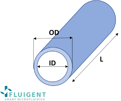
- “OD” means outer diameter.
- “ID” means inner diameter: Diameter of the fluidic path where fluid flows. The inner diameter plays a significant role in the resistivity brought by the tubing: the smaller it is, the more resistant the tubing will be.
- “L” means length. Usually, the microfluidic tubing is made as short as possible to have smaller internal volumes, the internal volume of the tubing being the inner section times the length of the tubing. It is also a parameter that takes part in the resistivity of the tubing.

Figure 1: Definition of tubing dimensions (OD, ID and L)
Microfluidic tubing fittings: Inches to millimeters conversion
Selecting the appropriate inner diameter is essential for controlling flow rates and minimizing dead volumes. Smaller inner diameters result in lower flow rates, while thicker tubing walls provide increased durability. Balancing these factors ensures optimal fluid dynamics within the microfluidic system.
In many catalogs, tubing dimensions can be displayed in inches, millimeters and mixture of the two. The following chart will help conversion between these two systems.
| Inches | Millimeters |
|---|---|
| 1 | 25.4 |
| 1/8″ | 3.17 |
| 1/16” | 1.58 |
| 0.040″ | 1 |
| 1/32” | 0.794 |
| 0.030″ | 0.75 |
| 0.020″ | 0.5 |
| 1/64″ | 0.397 |
| 0.010″ | 0.25 |
| 0.007″ | 0.175 |
| 0.005″ | 0.125 |
FAQ
- I have a 1/16’’ OD tubing. What does it mean?
It means the tubing has an outside diameter (OD) equals to 1/16’’inch (=1,58mm).
- I have a 1/32’’ OD tubing. What does it mean?
It means the tubing has an outside diameter (OD) equals to 1/32’’inch (=0,794mm).
- How to cut my tubing properly?
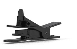
In order to get clean interface and prevent any clogging or collapsing of the fluidic path, all tubing should be cut with specifically designed cutters.

Material Compatibility
The choice of tubing material is crucial to prevent interference with the experimental setup or sample. Consider factors such as chemical compatibility, inertness, and resistance to solvents.
A wide range of materials are available for the same ID / OD combination. The material should be selected according to the nature of the reagents flowing through the tubing.
Be careful to check the chemical and biological compatibility of the tubing material before installing the tubing on your application. Chemical resistance is particularly critical when working with aggressive solvents or reactive reagents to prevent tubing degradation or alteration of experimental results.

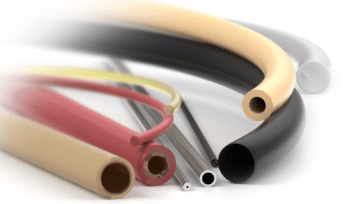
Some of the most common materials for microfluidic tubing include:
- PEEK (Polyetheretherketone): Biocompatible, chemically inert to most commonly used solvents, low non-specific adsorption. PEEK tubing is flexible, offers a very smooth internal surface and be easily cut to desired lengths. For low and high-pressure applications. Very small internal diameters available.
- PTFE (Polytetrafluoroethylene, equivalent to the brand name Teflon®): Chemically inert to most commonly used solvent, non-toxic, non-porous, excellent stress-resistance. Flexible and transparent. Mostly for low-pressure applications.
- FEP (Fluorinated ethylene-propylene): Same family as PTFE. Chemically inert to most used solvent and biocompatible. Flexible and transparent. Mostly for low-pressure applications.
- ETFE (Ethylene tetrafluoroethylene): Same family as PTFE and FEP but more rigid and better-suited to higher pressure applications.
- Fused silica (high-purity glass): Mainly for capillary tubing, exists with external diameters smaller than 1/32’’ (360 µm OD, 510 µm OD…). NB: this type of tubing must be cut with ceramic cutters to get clean inlet and outlet.
Low-pressure /high-pressure: With the regulated pressure provided by Fluigent pressure controllers, such as our Flow EZ™, or our OEM offers, going up to 100 psi (7 bars), all fittings and microfluidic tubing used with Fluigent devices can be rated as low-pressure.
Transparency and Visibility
For applications requiring visual observation or fluorescence microscopy, transparent tubing is essential. Materials like glass or certain polymers offer excellent transparency, enabling researchers to monitor fluid behavior and interactions within the microchannels.
Temperature Stability
For experiments involving temperature-sensitive samples or processes, choose tubing materials with adequate temperature stability. Some applications may require tubing that can withstand extreme temperatures without deformation or degradation.
Use sleeves or connectors to adapt your tubing
Consider the compatibility of the tubing with connectors and fittings. Standardization of connection methods facilitates integration into existing setups and ensures a secure, leak-free interface. Common connection types include barbed fittings, luer connectors, and threaded connections.
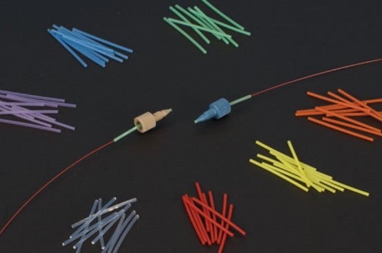
- Sleeves are small hollow cylinders; connectors are special fittings.
- For connecting 1/32’’ OD tubing to standard 10-32 coned port (1/16’’ OD).
- Different internal diameters are available.
- Example: The green sleeve provided with Fluigent FRP LQ KIT has the right internal diameter so that it can be slid over 1/32’’ tubing and has a 1/16’’ outer diameter. Thus, it makes a 1/32’’ tubing locally appear as a 1/16’’ tubing and makes it compatible with fittings designed for 1/16’’ tubing.

Conclusion
Selecting the right microfluidic tubing is a fundamental step in designing an efficient and reliable microfluidic system. Researchers should carefully consider material properties, dimensions, transparency, flexibility, sterilization methods, chemical resistance, connection compatibility, and temperature stability to ensure optimal performance in their specific applications. By adhering to these general guidelines, researchers can make informed decisions that contribute to the success of their microfluidic experiments.