Microfluidic Flow Sensing Technologies, A Review
Flow rate measurement is needed for many microfluidic applications, including microfluidic droplet generation, cell culture under flow, and organs on chip. Several technologies aim to provide accurate real time flow measurement to meet this need. In this review, the different existing microfluidic flow sensing solutions for low-flow liquids are described, with their advantages and current limits, as progress is still ongoing in this field.
The physical properties of the sample such as viscosity, density, conductivity, diffusion coefficient, solubility or phase equilibrium and flow conditions impact the measurement of the flow. The ideal flow sensor should provide accuracy and precision, function for a wide range of flow rates (from 1 nL/min to 10 mL/min for microfluidic applications), have a quick response time, and work with all types of liquid independently of the external conditions (temperature and humidity amongst others) all for a lower cost. We divided flow metering technologies into two main categories: active and passive flow sensors. Active sensors provide energy to the liquid and measure the changes they induce. They represent more than two-thirds of the flow sensors currently used in microfluidic applications. Passive sensors do not supply any energy to the fluid. Their principle is based on the evaluation of the disturbance the flow causes on the sensor. Each category can be divided into subcategories that are listed in the graph below.

Active Microfluidic Flow Sensing
Thermal Flow Meters1,2,3
The most widespread flow sensors in microfluidics rely on heat transfer measurement. They have one heating element and one or several sensing elements. The flow rate Ql can be derived from the fluid velocity v knowing the tube section S. The fluid velocity is linked to the heat loss Qh in accordance with the following equation, where a and b are constants that depend on the channel and the fluid and that can be determined empirically:

The heat loss is proportional to the dissipated power P that is known thanks to the temperature T detected by the sensor, where I is the intensity of the current, and α is the resistivity:

Three different acquisition methods exist for this active microfluidic flow sensing subcategory.
- Firstly, the hot-film anemometer consists of only one element that heats and measures. It can work in constant temperature mode or constant current mode. In the first case, a feedback loop maintains the sensor’s temperature constant and the flow rate is derived from the current needed to achieve that. In the second case, the flow rate is derived from the decrease of the sensor’s temperature as the flow rate increases.
- Secondly, the calorimetric flow meter consists of one heating element supported by a constant current and surrounded by two sensing elements that measure the asymmetry of the temperature profile caused by the flowing liquid. Unlike the hot-film anemometer, it gives information on the flow direction and consumes less power. This technology is used in Fluigent’s flow units (research) or flow sensors (industrial) as it offers the best performance in active flow sensors. They saturate over a certain flow rate due to the limited transfer of heat between the fluid and the heater/sensor which restricts their dynamic range to 1 order of magnitude.
- Lastly, the time-of-flight flow meter consists of one heating element, and a sensor that evaluates the flow rate based on the time needed by a heat pulse to travel a known distance. Due to its structural asymmetry, it cannot deal with liquids passing in both directions, because the flow must pass by the heater before passing by the sensor for the latter to detect the heat pulse. It is the lesser-developed thermal flow sensing method as temperature diffusion along the channel disturbs the heat pulse.

Advantages and limits
MEMS thermal flow sensors are considered one of the most mature microfluidic flow sensing technologies. They are highly responsive (1 ms to 1s), making them ideal for complex protocols such as imitating aspects of an in vivo cellular microenvironment with heartbeats or shear stress.
Regarding the ideal flow meter described at the beginning of the review, thermal flow meters lack being liquid-independent as the measurement is influenced by the thermal properties of the liquid, thus requiring a calibration step. For example, droplet production is a process that involves oils, surfactants and samples with different properties. For that application, the user is forced to calibrate the thermal sensor once per manipulation with a different liquid.
Their use can be problematic when manipulating temperature sensitive samples like biological samples. Improving these sensors’ sensitivity requires bringing the sensors closer to the heater, impacting the manufacturing cost. Another solution is to reduce the channel’s internal diameter, but this can lead to clogging, notably when manipulating liquids with cells or beads. For instance, eukaryotic cells range between 1 and 100 µm, so they can be incompatible with our sensor model that measures flow rates below 1,5 µL/min because it has an internal diameter of 25 µm. One must also be careful when manipulating cells of the materials constituting the channel. Moreover, when used during long periods, a biofilm can form and alter the measurement.
Coriolis Flow Meters1,4
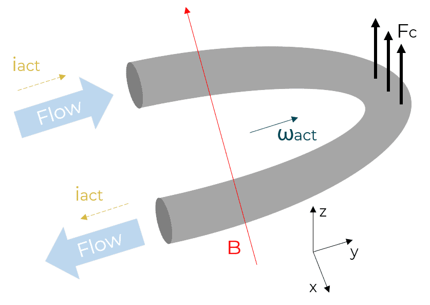
An alternative to thermal microfluidic flow sensing is to use a Coriolis flowmeter. The flow rate measurement is based on the detection of the movement caused by the Coriolis force in a U-shaped conductive channel. Running an alternative current iact in the conductor submitted to a constant magnetic field B induces a periodical Lorentz force FL along the z axis that drives the channel with an angular velocity ωact. As fluid flows through the channel, a Coriolis force FC along the z axis that is proportional to the mass flow Φm and the angular velocity ωact is created:

This causes a second vibration mode with an angular velocity ωd. The flow rate Q is computed thanks to the optical measurement of the amplitude of both oscillations and several parameters linked to the microchannel, the operating modes and the detection-mode modal spring constant.

Advantages and limits
Unlike thermal sensors, Coriolis sensors do not need calibration and are not affected by the liquid density in microfluidic applications as long as it is between 1 and 2 kg/m3. They can measure the density and flow rates with over 3 ranges of magnitude, but they also increase the liquid’s temperature by several degrees so it can be an obstacle for certain applications that require microfluidic flow sensing. The major drawbacks are currently the price (a few thousand euros) and the long tubing (due to the small internal diameter the fluid has to go through) that is prone to clogging.
Passive Microfluidic Flow Sensing
As of today, only active flowmeters are industrialized on a large scale. They are either adapted from other applications or inspired by natural phenomena. They aim to save power by taking advantage of the energy created by the fluid flowing. They have been tested for research purposes but are not commercialized for microfluidic applications yet.
Fluid/Structure Interaction Flow Meters1,5,6
These flow sensors operate through the dissipated energy of the flowing liquid that leads to the motion or deformation of their body. Three technologies are featured below.
- Firstly, the differential pressure flowmeter computes the flow rate Q from the pressure difference Δp applied at the inlet and the outlet of the channel knowing its dimensions and the liquid viscosity, with the following formula, where Rh is the hydrodynamic resistance that can be obtained through a calibration step:
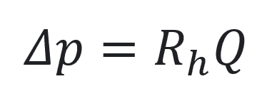
The pressure acquisition is done thanks to a deformable membrane or diaphragm with piezoresistive material deposited on it or with capacitive readouts. These flowmeters do not have an effect on the flow, but if they are contaminated, up to 20% of errors are caused by hydrodynamic resistance variations and mechanical properties variations of the membrane. They are more adapted to pneumatic paths than fluidic paths.
- Secondly, the cantilever-based flowmeter detects the distortion of a cantilever beam immersed perpendicularly to the flow. Its behavior mimics hair-cells or cilia. The beam bends under the drag force exerted by the fluid and the longitudinal strain is measured by piezo resistors at its base. The flow rate Q is proportionate to the fluid (viscosity µ and) velocity v, which is proportionate to the drag force obtained by integrating the stress [σ], which is strongly intertwined with the strain detected:

This microfluidic flow sensing technology allows a better measurement dynamic range than differential pressure. Moreover, as they are made thanks to MEMS techniques, cantilever sensors can be compact and in the same price range than thermal flowmeters. Like them, they also need to be calibrated for each liquid. But the beam can wear out or break if the drag force is too strong, and be affected if covered by particles, cells, bubbles or proteins contained in the flow.
- Lastly, the particle seeding flowmeter measures the velocity of particles that were seeded into the flow thanks to particle image velocimetry or laser Doppler velocimetry, two optical detection methods. The first one is based on the comparison between two successive images taken with a specified delay, and the latter on the interference fringe created by two intersecting coherent laser beams. Limitations of the device include difficulty being integrated in a microfluidic setup due to the bulk optical detection devices and its requirement for transparent microfluidic channels.

Advantages and limits
These technologies are compatible with temperature sensitive samples, have low power consumption and have low effects on the flow conditioning, but they are based on prior knowledge of the liquid and are prone to contamination issues as the test bodies are in contact with the fluid. The concerns for their invasiveness, reliability, and repeatability prevent fluid/structure interaction sensors from being competitive with active flow sensors.
Non-invasive Flow Meters1,5,7
Until this point, all the flow sensors reviewed had an impact on the liquid, whether through a contamination risk or a rise in temperature. Moreover, their price does not allow them to be considered as disposable products whereas biological applications often prefer Fluigent components that can be sterile or disposable. The following will focus on inconsequential microfluidic flow sensing methods.
Fluigent non-invasive flow sensing technology
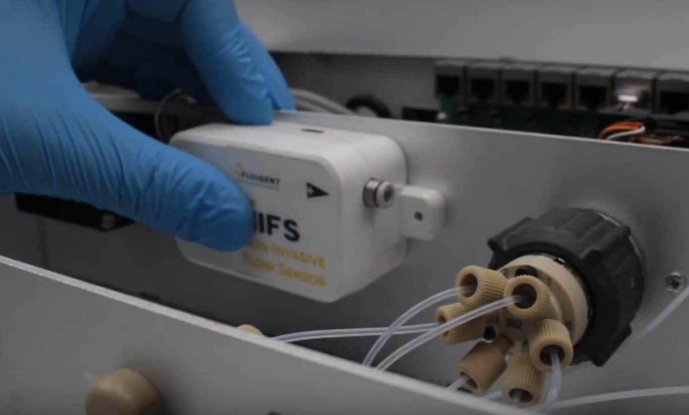
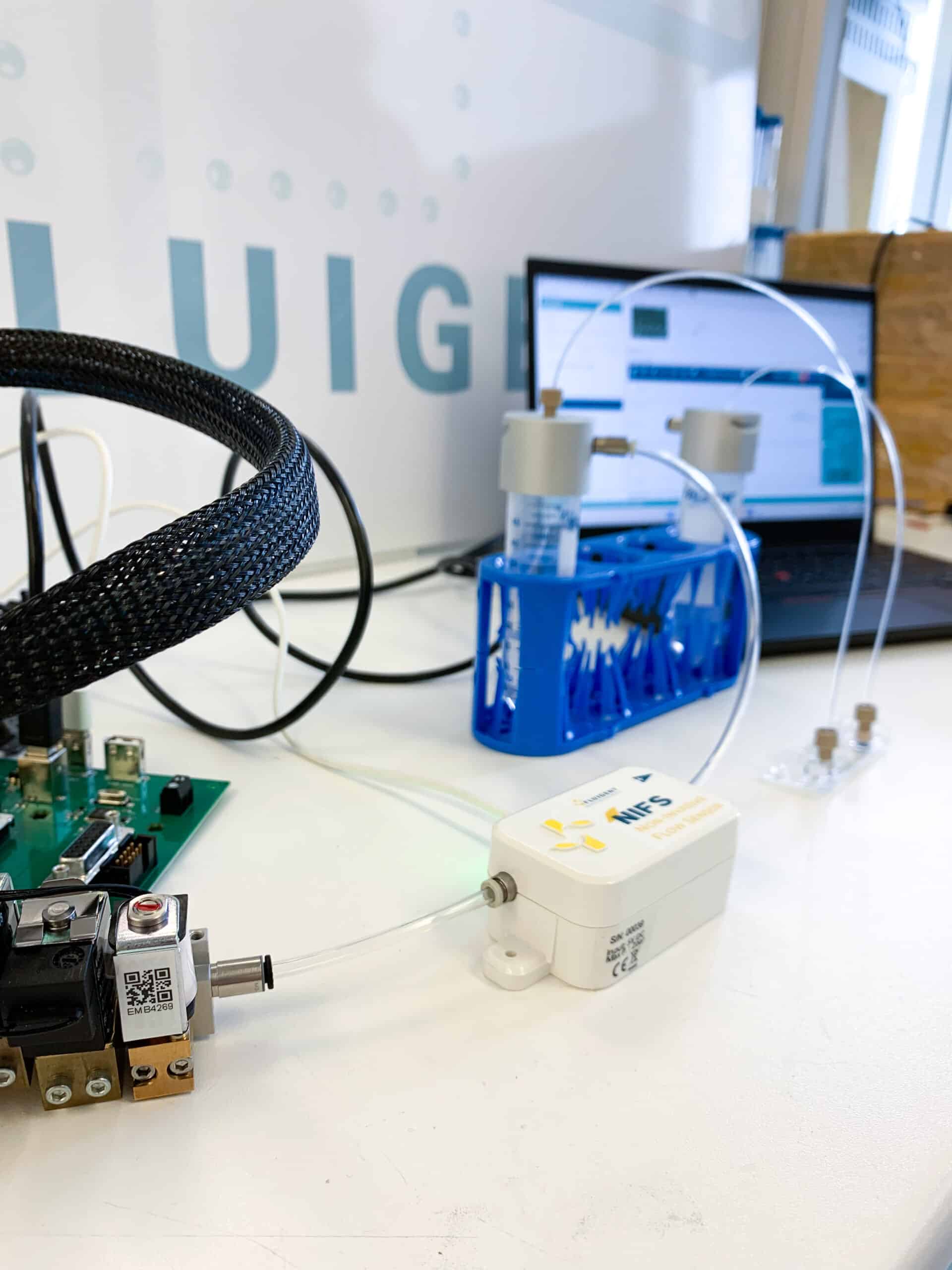
Fluigent internally worked on a flow sensing technology dedicated to pressure-based microfluidics. It will be the first non-invasive and calibration-free flow sensing technology for microfluidic applications. The device will be placed in the pneumatic path between the pressure controller and the fluidic reservoir. The liquid flow rate will be derived from the gas flow rate in the pneumatic path thanks to calibrations and sensors, high-performance algorithms, and a zero-leakage system.
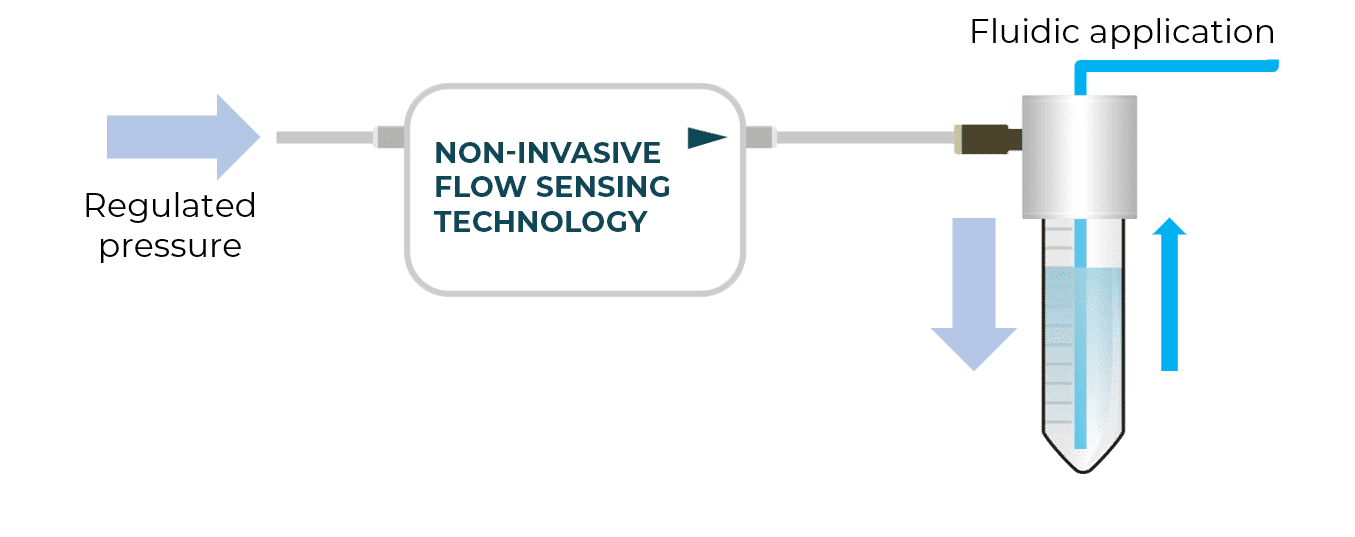
As it’s not positioned in the fluidic line, the device will be able to tackle all contamination and clogging issues as well as time-consuming liquid calibration and cleaning steps. It shows high accuracy and is liquid independent. They will be thus adapted to perform experiments with a sterile environment for the fluid or to produce droplets using several different liquids.
However, the response time will be < 10 s, making it incompatible if one needs to generate complex flow patterns during a specific timeline. In addition, gas flow calibration needs to be performed if one is not using air in the pneumatic path.
Three other technologies have been selected for this review. They are less developed than the others for now and still need improvement to be effective.
- Firstly, the gravimetric flow meter gives the flow rate according to the liquid mass increment per unit time in the reservoir, with knowledge of the liquid density. It’s not adapted to observe quick flow rate fluctuations because of its low acquisition frequency of a scale. The interaction between the outlet of the reservoir and the liquid in it is a major source of error.
- Secondly, the front meniscus tracking flowmeter principle consists in optically following the meniscus displacement of the liquid flowing in a capillary during a time interval, but it can only be set at the outlet of the microfluidic circuit, limiting its use. Other types of microfluidic flow sensing methods by optical tracking have been tested but the optical devices needed to carry them, making it impossible to integrate them in a compact setup.
- Lastly, the acoustic flow meter determines the flow rate with the help of ultrasonic signals that propagate in the channel. The concept is the same as the thermal time-of-flight sensor: the propagation time of ultrasonic pulses is processed by cross-correlation. It has the benefit of being independent of the fluidic properties but is expensive, has limited possibilities of footprint optimization due to the geometrical constraints the device must respect, and has sensitivity issues for the low microfluidic flow ranges (these sensors are commercialized for flow rates above 100 mL/min), and for liquids that are prone to cavitation or dissolution.
Comparative summary between microfluidic flow sensing methods
| Flowmeter1,5,6,7 | Range (µL/min) | Accuracy (% of reading) | Response time (s) | Estimated volume (cm3) | Materials that might be in contact with water | Estimated price (€) |
| Hot-film anemometer | 0.02 – 167 | 20 – 5 | 0.01 – 0.02 | 50 | PEEK, Quartz Glass, PPS, stainless steel, ETFE | 100 – 2 000 |
| Calorimetric | 0.07 – 1 000 | 10 – 2.5 | 0.04 | 50 | PEEK, Quartz Glass, PPS, stainless steel, ETFE | 100 – 2 000 |
| Time-of-flight | 10 – 1 000 | 6 | 0.012 | 50 | PEEK, Quartz Glass, PPS, stainless steel, ETFE | 100 – 2 000 |
| Coriolis | 0.84 – 3 300 | 0.2 | 0.2 | 400 | Silicon microtube or silicon-rich silicon nitride tube | 2 000 – 4 000 |
| Differential pressure | 1.1 – 1 100 | 10 | 0.1 | 1 000 | Silicon nitride membrane or diaphragm | 250 – 1 000 |
| Cantilever | 2 – 500 | 0.1 | 0.01 | 400 – 50 000 | Beam in silicon nitride, SU8, and polydimethylsiloxane (PDMS) | 400 – 5 000 |
| Particle seeding | 0.001 – 54 | 5 – 2 | 1 | > 100 000 | Particles (ex : 1 µm diameter polystyrene spheres) | > 10 000 |
| Gravimetric | 0.017 – 10 000 | 6 – 0.05 | 2 – 20 | > 100 000 | Non invasive | > 10 000 |
| Front meniscus tracking | 5 – 100 | 2 | 300 | 50 000 | Non invasive | 4 000 – 8 000 |
| Acoustic | 200 – 1 600 | 1 – 0.1 | 0.01 | 100 – 1 000 | Non invasive | N/A |
Conclusion
Factors that are elusive with conventional fluidic metering (liters per minute), such as the channel and fluid interactions, cavitation (formation of bubbles) and dissolution (multi-phase flows) become critical at the micrometer scale level, making microfluidic flow sensing more challenging.
Different technologies have been developed to address the above challenges with all showing specific advantages and limitations but research in flow rate measurement will greatly help the progression of many microfluidic applications such as personalized medicine through drug delivery or research in life science through organ-on-a-chip.
References
[1] C. Cavaniol, W. Cesar, S. Descroix, J.-L. Viovy, “Flowmetering for microfluidics”, Lab on a Chip, 2022
[2] N. T. Nguyen, “Micromachined flow sensors – a review”, Flow Measurement and Instrumentation, 1997
[3] B. Mimoun, A. van der Horst, R. Dekker, D. van der Voort, M. Rutten, F. van der Vosse, “Thermal Flow Sensors on Flexible Substrates for Minimally Invasive Medical Instruments”, Sensors, 2012
[4] R. Smith, D. R. Sparks, D. Riley, N. Najafi, “A MEMS-Based Coriolis Mass Flow Sensor for Industrial Applications”, Transactions On Industrial Electronics, 2009
[5] L. Huang, “Microfluidic Flow Sensing Approaches”, Advances in Microfluidics and Nanofluids, 2021
[6] P. Salipante, S. D. Hudson, J. W. Schmidt, J. D. Wright, “Microparticle tracking velocimetry as a tool for microfluidic flow measurements”, Experiments in Fluids, 2017
[7] M. Takamoto, H. Ishikawa, K. Shimizu, H. Monji, G. Matsui, “New measurement method for very low liquid flow rates using ultrasound”, Flow Measurement and Instrumentation, 2001
