Microfluidic Resistance
Flow resistance is a key parameter in every microfluidic experiment. In biomechanics, it will affect the induced shear stress of the flow, and hence the physiological environment of cells. In droplet microfluidics and general microfluidics experiments, it will determine the range of flow rates achievable in the system, based on the range of pressure that can be applied by the pressure flow controller being used. It is therefore essential to calculate the microfluidic flow resistance of a chip in order to fully understand the system and define the flow parameters.
Introduction to microfluidic flow resistance
Hydrodynamic resistance, or flow resistance, can be defined as the opposition offered by a fluidic element (tubing, channels, valves…) to the flow itself. When pressure is applied to a fluid, the flow resistance will determine the associated flow rate. By tuning the flow resistance of the system, the range and precision of the flow rate can be controlled.
In a microfluidic set-up, we can calculate two distinct kinds of hydraulic flow resistance, depending on the impact they have on the experiment:
External flow resistances
This is induced by the tubing and fittings used to connect the microchip to the microfluidic flow control system (pressure pump, syringe pump, etc.). By tuning the tubing material, length and diameter, this kind of resistance may offer an easy and powerful way to enhance or adjust the performance of flow control systems.
Internal flow resistances
This results from the microchip design. Internal flow resistance management may be used, e.g. with a passive flow control system: In many applications, microfluidic circuits are designed to provide dedicated functions such as a gradient generator, droplet merging and splitting, passive valves, cell trapping, and so on.
How to calculate microfluidic flow resistance
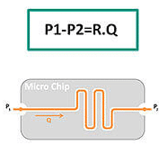
Microfluidic flows are characterized by the prevalence of viscous effects compared to inertia. From a physics point of view, this behavior corresponds to a low Reynolds number indicating laminar flow, leading to a drastic simplification of the complex Navier-Stokes equations describing fluid displacement. The result is a very simple equation linking:
- Mean flow-rate Q
- Pressure drop (change in P)
- Microfluidic resistance R

Just as the electrical potential drop dV is proportional to intensity A, fluid pressure drop dP is proportional to the mean flow rate Q. In both cases, a resistance R can be defined as the proportional coefficient.
This analogy points out that the microfluidic resistance quantifies an energy drop along the microfluidic channels. As in an electrical network, equivalent microfluidic resistances can be calculated to simplify modeling of complex microfluidic devices or Lab-On-Chip devices with multiple parallel and/or series channels.

Resistance formula
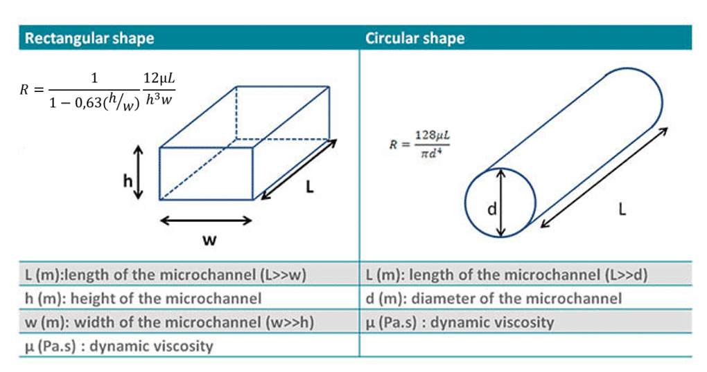
It is possible to calculate microfluidic flow resistance for channels with simple or common cross-sections, such as circular or rectangular shapes. For these shapes, the formula directly links microfluidic resistance with:
- Channel geometry
- Fluid characteristics

Related content
- Microfluidics White Papers
An exploration of Microfluidic technology and fluid handling
Read more - Support & Tools
Pressure & Flow Rate Calculator
Read more 
5 reasons to choose OEM pressure controllers over OEM syringe pumps for microfluidic applications
Read more- Expert Reviews: Basics of Microfluidics
Choosing the Right Microfluidic Pressure Range
Read more - Expert Reviews: Basics of Microfluidics
Selecting Microfluidic Tubing
Read more
