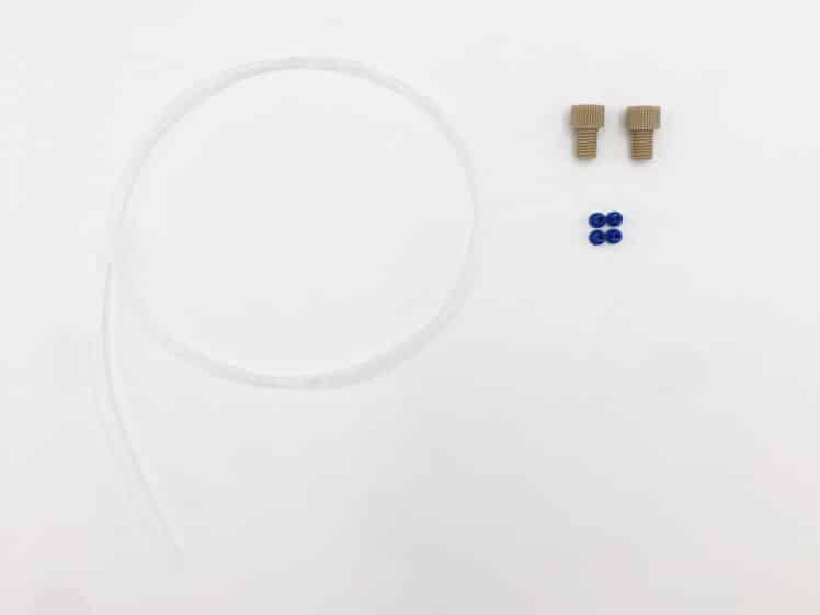
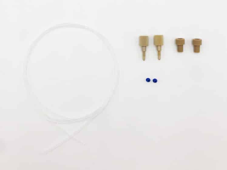
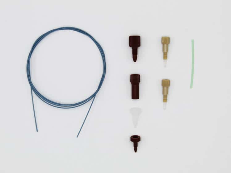
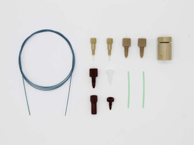
Uses minimum bench space
Bidirectional Microfluidic Flow Sensor
- Best Seller
FLOW UNIT | FLOW UNIT +
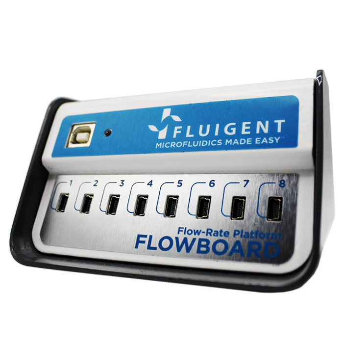
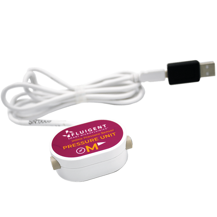
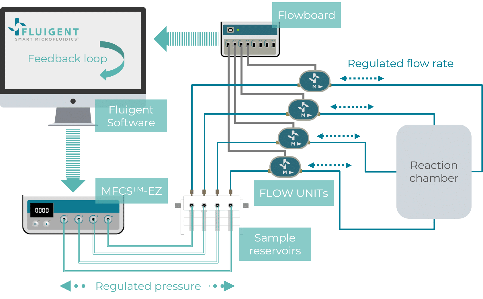
The FLOW UNIT and FLOW UNIT+ are bidirectional microfluidic flow sensors compatible for stand-alone use with the Line Up™ controller or other microfluidic control systems such as the MFCS™ series using the Flowboard hub.
Available in multiple low rate ranges, the FLOW UNIT and FLOW UNIT + Microfluidic Flow Sensor allows for pressure regulation using the DFC (Direct Flow Control) algorithm to monitor or control the system by flowrate instead of pressure.
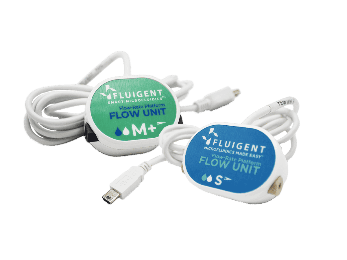
- Compact
- Adaptable
Use with or without a PC
- Intuitive
Straight forward set up & use
- Wide range
Measurement from nL to mL
Features of the flow rate sensor
Tune Measurements for Various Liquids
When combined with a FLOW UNIT, a scale factor can be added to your measurements when handling other fluids than the liquid for which the flow rate sensor is calibrated for.
For organic solutions, a second calibration with isopropyl alcohol is built-in on the FLOW UNIT models S, M+ and L+.
Flow Rate Measurement
The FlOW UNIT and FLOW UNIT+ enable fast and accurate measurements of ultra-low liquid flow rates.
Monitor & Control Experiments
Flowrate measurements (bidirectional) for all FLOW UNITs are displayed in FLUIGENT software. An additional function displays and records the dispensed volume for each FLOW UNIT Microfluidic Flow Sensor. Flowrates can be directly controlled with the MFCS™ series and LineUp™ series instruments using the DFC, a “self-learning” flow rate control algorithm.
Precision for Various Flow Rate Ranges
The different FLOW UNIT models offer an extensive choice of flowrate ranges to best match your needs over the range of 7nL/min to 5mL/min.
Locally Control Flow Rate
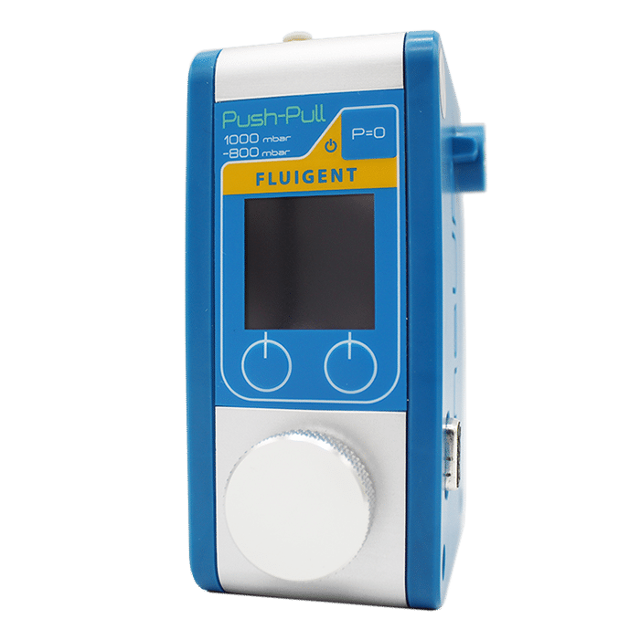
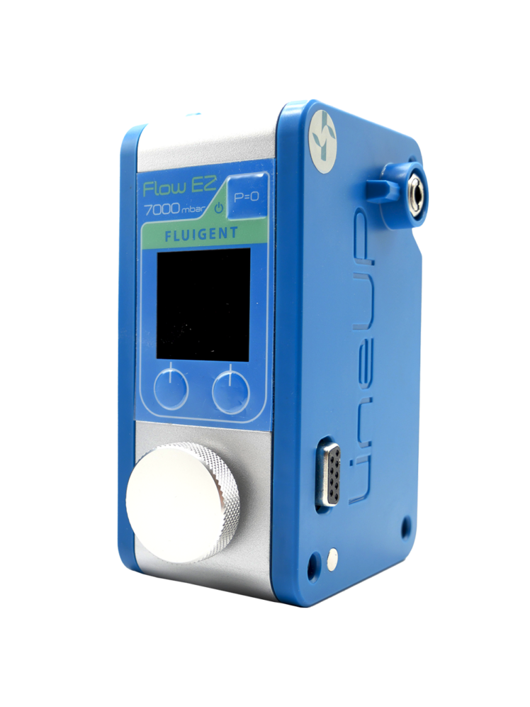
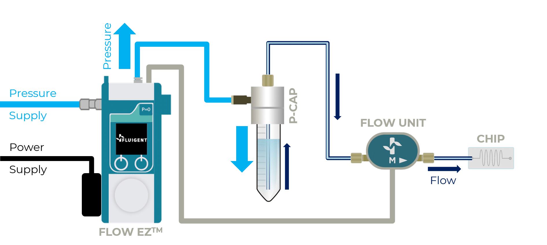
Combined with a LineUp™ Push-Pull or a LineUp Flow EZ™, one can monitor or control flow rate without a PC.
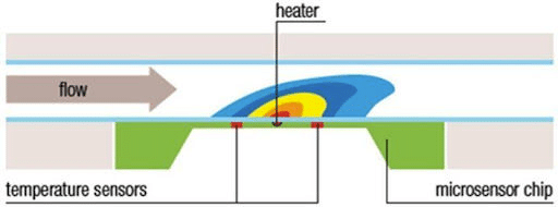
How does the flow rate sensor work?
Fluigent’s Microfluidic Flow Sensor is a unique tool to easily monitor flow rates in any microfluidic system with the best precision and accuracy. A microheater provides a minimal amount of heat to the medium monitored. Two temperature sensors, located on both sides of the heat source, detect temperature variations.
The high precision thermal sensor technology provides total media isolation and very low internal volume with no moving parts. The flow rate is then calculated based on the thermal desorption, which is directly related to the flow rate.
Specifications
Sensor performance
| Sensor model | XS | S | M+ | L+ |
| Part Number | FLU-XS | FLU-S-D | FLU-M+ | FLU-L+ |
| Calibrated media | Water | Water IPA | Water IPA | Water IPA |
| Range | Water 0±1.5µL/min | Water 0±7µL/min IPA 0±70µL/min | Water, IPA 0±2mL/min | Water, IPA 0±40mL/min |
| Accuracy (m.v.= measured value) also applies to negative values | Water 10% m.v. above 75 nL/min 7.5 nL/min below 75 nL/min | Water 5% m.v. above 0.42 µL/min 21 nL/min below 0.42 µL/min IPA 20% m.v. above 4.2 µL/min 210 nL/min below 4.2 µL/min | Water 5% m.v. above 10 µL/min 0.5 µL/min below 10 µL/min IPA 10% m.v. above 50 µL/min 5 µL/min below 50 µL/min | Water 5% m.v. above 1 mL/min 50 µL/min below 1 mL/min IPA 10% m.v. above 2 mL/min 200 µL/min below 2 mL/min |
| Lowest detectable flow increment | 3.7 nL/min | 10 nL/min | 0.25 µL/min | 25 µL/min |
| Repeatability | Water <1% m.v. above 90 nL/ min 0.9 nL/min below 90 nL/min | Water 0.5% m.v. above 0.7 μL/ min 3.5 nL/min below 0.7 μL/ min IPA 1% m.v. above 0.7 μL/ min 7 nL/min below 0.7 μL/ min | At 23°C Water & IPA 0.5% mv above 100μL- min 0.5μL/min below 100μL/ min | At 23°C Water & IPA 0.5% mv above 2mL/ min 10μL/min below 2mL/ min |
Mechanical specifications
| Sensor model | XS | S | M+ | L+ |
| Sensor inner diameter | 25 µm | 150 µm | 400 µm | 1.4 mm |
| Maximum pressure | 200 bar | 200 bar | 12 bar | 12 bar |
| Wetted materials | PEEK & Quartz Glass | PEEK & Quartz Glass | PPS, stainless steel 316L Fittings: PEEK/ ETFE | PPS, stainless steel 316L Fittings: PEEK/ ETFE |
| Inner volume | 1µL | 1.5µL | ~ 28µL | ~ 58µL |
| Fluid connector ports | UNF 6-40 for 1/32” OD tubing | UNF 6-40 for 1/32” OD tubing | UNF 1⁄4′′-28 flat bottom for 1/16” OD tubing | UNF 1⁄4′′-28 flat bottom for 1/16” OD tubing |
| Weight | 97 g | 97 g | 97 g | 97 g |
Sensor performance
| Sensor model | XS | S | M | L | XL |
| Part Number | FLU-XS | FLU-S-D | FLU-M-D | FLU-L-D | FLU-XL |
| Calibrated media | Water | Water IPA | Water IPA | Water IPA | Water |
| Range | Water 0±1.5µL/min | Water 0±7 µL/min IPA 0±70 µL/min | Water 0±80µL/min IPA 0±500µL/min | Water 0±1mL/min IPA 0±10mL/min | Water 0±5mL/min |
| Accuracy (m.v.= measured value) also applies to negative values | 10% m.v. above 75 nL/ min 7.5 nL/min below 75 nL/ min | Water 5% m.v.above 0.42 µL/min 21 nL/min below 0.42 µL/min IPA 20% m.v. above 4.2 µL/min 210 nL/min below 4.2 µL/min | Water 5% m.v. above 2.4 µL/min 0.12 µL/min below 2.4 µL/min IPA 20% m.v. above 25 µL/min 5 µL/min below 25 µL/min | Water 5% m.v. above 0.04 mL/min 1.5 µL/min below 0.04 mL/min IPA 20% m.v. above 0.5 mL/min 100 µL/min below 0.5 mL/min | 5% m.v.above 0.2 mL/min 10 µL/min below 0.2 mL/min |
| Repeatability (m.v.= measured value) also applies to negative values | <1% m.v. above 90 nL/ min 0.9 nL/min below 90 nL/min | Water 0.5% m.v above 0.7µL/min 3.5 nL/min below 0.7 µL/min IPA 1% m.v above 0.7µL/min 7 nL/min below 0.7 µL/min | Water 0.5% m.v above 1.6 µL/min 8 nL/min below 1.6 µL/min IPA 1% m.v above 25 µL/min 0.25 µL/min below 25 µL/min | Water 0.5% m.v above 40 µL/min 0.2 µL/min below 40 µL/min IPA 1% m.v above 500 µL/min 5 µL/min below 500 µL/min | 0.5% m.v. above 200 µL/ min 0.4 µL/min below 200 µL/min |
| Lowest detectable flow increment | 3.7 nL/min | 10 nL/min | 0.06 µL/min | 0.7 µL/min | 3 µL/min |
Mechanical specifications
| Sensor model | XS | S | M | L | XL |
| Sensor inner diameter | 25µm | 150 µm | 430 µm | 1.0 mm | 1.8 mm |
| Total internal volume | 1 µL | 1.5 µL | 5 µL | 25 µL | 80 µL |
| Maximum pressure | 200 bar | 200 bar | 100 bar | 15 bar | 15 bar |
| Wetted materials | PEEK and Quartz Glass | PEEK and Quartz Glass | PEEK and Borosilicate Glass | PEEK and Borosilicate Glass | PEEK and Borosilicate Glass |
| Fluid connector ports | UNF 6-40 for 1/32” OD tubing | UNF 6-40 for 1/32” OD tubing | UNF 6-40 for 1/32” OD tubing | Flangeless fitting 1/4-28 | Flangeless fitting 1/4-28 |
| Weight | 97 g | 97 g | 97 g | 97 g | 97 g |
OxyGEN
| Control in real-time, protocol automation, data record and export |
| ver. 2.2.0.0 or more recent |
Software Development Kit
| Custom software application |
| ver. 22.2.0.0 or more recent |
Warning :
When using biomaterials such as cell or bacteria for a long period, a biofilm may form over time on the Flow Unit’s channel impacting the accuracy of measurements. Regular cleaning and monitoring are recommended to ensure accurate and reliable results.
For long term experiment we encourage the use of the Flow unit standard rather than the Flow unit which is more sensitive to biofilm formation.
Expertise & resources
-
Fluigent products manual Cleaning Procedure Flow Units Download
-
Microfluidics case studies CNRS/UTC: study of a liver-on-a-chip model Read more
-
Fluigent products manual Fluigent Flow-Rate Platform User Manual Download
-
Fluigent products manual FlowBoard and FLOW UNIT+ User Manual Download
-
Fluigent Products Datasheets FLOW UNIT+ Datasheet Download
-
Microfluidics case studies University of Cambridge: Microfluidic GUV production and testing Read more
-
Microfluidic Application Notes Generating a water emulsion in an oil solution using a droplet generator chip Read more
-
Fluigent Products Datasheets FLOW UNIT Datasheet Download
-
Microfluidic Application Notes Impedance Measurement of Microbeads Read more
-
Expert Reviews: Basics of Microfluidics Flow control for droplet generation using syringe pumps and pressure-based flow controllers Read more
-
Expert Reviews: Basics of Microfluidics Microfluidic Flow Control: Comparison between peristaltic, syringe and pressure pumps for microfluidic applications Read more
-
Microfluidics case studies University of Maryland: Microfluidic System for Robotic that can Play Nintendo Read more
